
광모듈 기본 소개
광 모듈은 광전자 장치, 기능 회로 및 광 인터페이스로 구성됩니다. 광전자 장치는 전송과 수신이라는 두 부분으로 구성됩니다. 즉, 광 모듈의 기능은 송신단에서 전기 신호를 광 신호로 변환하는 것입니다. 광신호가 광섬유를 통해 전송된 후 수신단에서는 광신호를 전기신호로 변환합니다.
전송 부분은 특정 비트율의 입력 전기 신호를 내부 구동 칩에 의해 처리한 다음 반도체 레이저(LD) 또는 발광 다이오드(LED)를 구동하여 해당 속도의 변조된 광신호를 방출합니다. 내부 광전력 자동 제어 회로가 장착되어 출력 광신호 전력을 안정적으로 유지합니다.
수신 부분은 다음과 같습니다. 특정 비트 전송률의 광 신호 입력 모듈은 광 감지 다이오드에 의해 전기 신호로 변환되고 해당 비트 전송률의 전기 신호는 프리 앰프 이후에 출력됩니다.
-광모듈의 기본 개념-
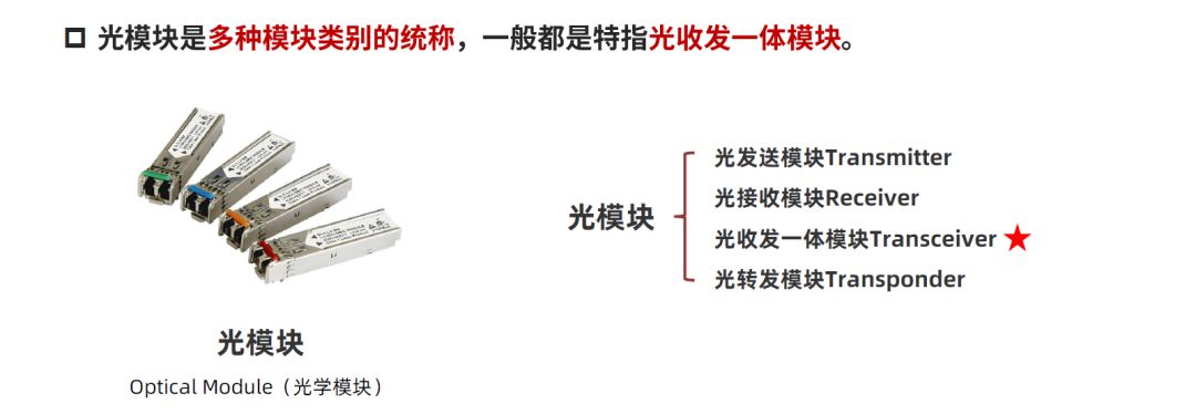
포트 광 모듈은 다양한 모듈 범주의 일반적인 이름으로, 일반적으로 광 트랜시버 통합 모듈을 나타냅니다.
-광모듈의 기능-

그 기능은 단순히 광 신호와 전기 신호 간의 변환을 실현하는 것입니다.
-광학 모듈 구조-
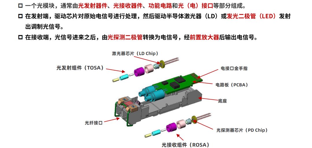
광 모듈은 일반적으로 광 송신기, 광 수신기, 기능 회로 및 광(전기) 인터페이스로 구성됩니다.
송신기에서는 드라이버 칩이 원래의 전기 신호를 처리한 후 반도체 레이저(LD)나 발광 다이오드(LED)를 구동하여 변조된 광신호를 방출합니다.
포트는 수신 측에 있습니다. 광신호가 들어온 후 광검출 다이오드에 의해 전기신호로 변환되어 프리앰프를 거쳐 전기신호로 출력됩니다.
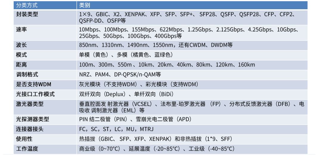
-광학 모드 분류-
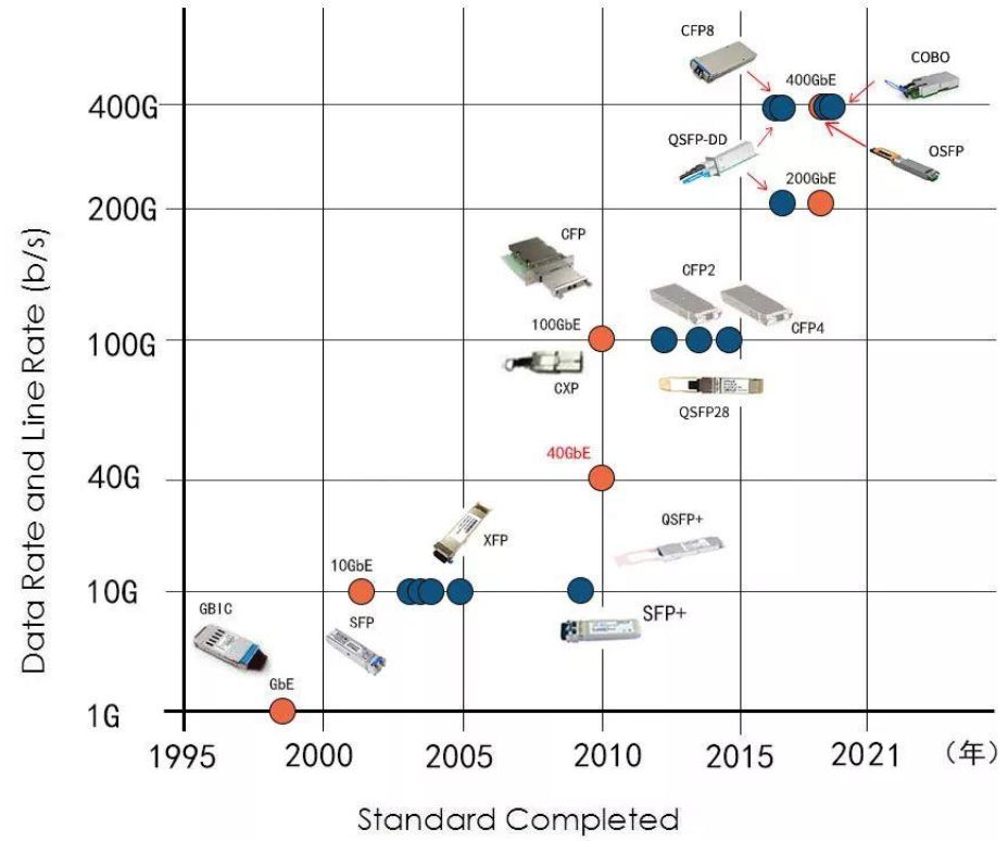
-광학모드의 개발 이력-
-광모듈 패키징 소개-
주로 다음과 같은 이유로 광학 모듈에 대한 다양한 패키징 표준이 있습니다.
》광섬유통신기술의 발전속도가 너무 빠르다. 광 모듈의 속도는 증가하고 부피도 줄어들어 몇 년마다 새로운 포장 라벨이 발행됩니다.
정확성 새로운 포장 표준과 기존 포장 표준 간의 호환성도 어렵습니다.
》광 모듈의 적용 시나리오는 다양합니다. 사용되는 다양한 유형의 광섬유에 따라 전송 거리, 대역폭 요구 사항 및 사용 장소가 다르며 광학 모듈도 다릅니다.

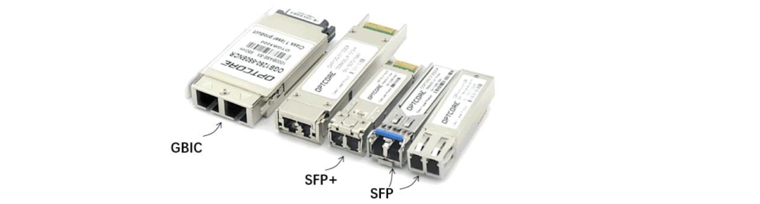
포트 GBIC
GBIC는 기가 비트레이트 인터페이스 변환기입니다.
2000년 이전에는 GBIC가 가장 널리 사용되는 광 모듈 패키징이자 가장 널리 사용되는 기가비트 모듈 형태였습니다.

포트 SFP
GBIC의 크기가 크기 때문에 나중에 SFP가 등장하여 GBIC를 대체하기 시작했습니다.
Small Form-factor Pluggable의 전체 이름인 SFP는 소형 핫스왑형 광 모듈입니다. GBIC 패키징에 비해 크기가 작습니다. SFP의 크기는 GBIC 모듈에 비해 절반으로 작으며, 동일한 패널에 2배 이상의 포트를 구성할 수 있습니다. 기능면에서는 둘 사이에 차이가 거의 없으며 둘 다 핫플러그를 지원합니다. SFP가 지원하는 최대 대역폭은 4Gbps입니다.

경구 XFP
XFP는 한눈에 이해할 수 있는 10기가비트 소형 폼팩터 플러그형 제품입니다. 10기가비트 SFP입니다.
XFP는 Xenpak 및 그 파생 제품을 대체할 수 있는 XFI(10Gb 직렬 인터페이스)로 연결된 전속 단일 채널 직렬 모듈을 채택합니다.

포트 SFP+
SFP+는 XFP와 마찬가지로 10G 광 모듈입니다.
SFP+의 크기는 SFP의 크기와 동일합니다. XFP보다 크기가 더 작고(약 30% 감소) 전력 소모도 더 적습니다(일부 신호 제어 기능으로 감소).
O SFP28
25Gbps 속도의 SFP는 주로 당시 40G 및 100G 광 모듈이 너무 비싸서 이러한 절충 전환 방식이 만들어졌습니다.

QSFP/QSFP+/QSFP28/QSFP28-DD
쿼드 소형 폼 팩터 플러그형, 4채널 SFP 인터페이스. XFP의 많은 성숙한 핵심 기술이 이 디자인에 적용되었습니다. QSFP는 속도 × 10G QSFP+, 4 × 25G QSFP28, 8 × 25G QSFP28-DD 광 모듈 등에 따라 4개로 나눌 수 있습니다.
4 × 25GE 액세스 포트에 적용할 수 있는 QSFP28을 예로 들어 보겠습니다. QSFP28을 사용하면 40G 없이 25G에서 100G로 업그레이드할 수 있어 케이블 연결의 어려움을 크게 단순화하고 비용을 절감할 수 있습니다.

QSFP/QSFP+/QSFP28/QSFP28-DD
2016년 3월에 설립된 QSFP-DD는 "Double Density"를 의미합니다. QSFP의 4개 채널에 한 줄의 채널을 추가하여 8개 채널로 변경합니다.
QSFP 방식과 호환될 수 있습니다. 원래 QSFP28 모듈을 계속 사용할 수 있습니다. 다른 모듈을 삽입하기만 하면 됩니다. OSFP-DD의 골드 핑거 수는 QSFP28의 두 배입니다.
각 QSFP-DD는 25Gbps NRZ 또는 50Gbps PAM4 신호 형식을 채택합니다. PAM4를 사용하면 최대 400Gbps를 지원할 수 있습니다.

OSFP
OSFP(Octal Small Form Factor Pluggable), "O"는 "octal"을 의미하며 2016년 11월 공식 출시되었습니다.
8개의 전기 채널을 사용하여 400GbE(8*56GbE, 단 56GbE 신호는 PAM4 변조 하에서 25G DML 레이저로 구성)를 구현하도록 설계되었으며 크기는 QSFP-DD보다 약간 더 큽니다. 와트수가 더 높은 광학 엔진과 트랜시버는 열 방출 성능이 약간 더 좋습니다.

CFP/CFP2/CFP4/CFP8
Centum 기가비트 형태의 플러그형, 고밀도 파장 분할 광통신 모듈입니다. 전송 속도는 100-400Gbpso에 도달할 수 있습니다.
CFP는 SFP 인터페이스를 기반으로 설계되었으며 크기가 더 크고 100Gbps 데이터 전송을 지원합니다. CFP는 단일 100G 신호와 하나 이상의 40G 신호를 지원할 수 있습니다.
CFP, CFP2 및 CFP4의 차이점은 볼륨입니다. CFP2의 용량은 CFP의 절반이고, CFP4는 CFP의 1/4입니다. CFP8은 400G용으로 특별히 제안된 패키징 형태로 크기는 CFP2와 동일하다. 25Gbps 및 50Gbps 채널 속도를 지원하고 16x25G 또는 8x50 전기 인터페이스를 통해 400Gbps 모듈 속도를 실현합니다.

게시 시간: 2023년 2월 14일